
Ok, so I redesigned my TEC controller to use the LTC1923 chip so I can use higher powers on the outputs. This isn’t ideal — I was already concerned with the size and part count for my current design. The new design uses a lot more parts. My current prototype uses 116 components and is much larger than prototype 1. But, let’s try it.
I decided I’d try breadboarding this first before I had a circuit board manufactured. This would allow me to experiment with component values easier, and make it easier to take measurements. Here’s what the prototype breadboard looked like:

Yeah, there’s a lot more parts. The old design had one chip, three transistors, one inductor and a bunch of passives. This one has five chips, eight transistors and two inductors. It’s going to be a tight fit.
So, does this do the trick? No way. TEC controllers are switch mode power supplies, and pretty high current ones at that. There’s no way on a solderless breadboard like this to cool surface mount components. The result is an absolute mess when it runs — if it runs at all. Noise is terrible and the power transistors start smoking after only a few seconds.
This wasn’t a total waste of time. There’s a really weird problem with the LTC1923 as it powers up. My power supply doesn’t deliver the full regulated voltage right away — it ramps up. There is a point at about 4.2V where the LTC1923 sends a short pulse to the output transistors. This pulse is shorting one of the legs of the H-Bridge, shorting the transistor directly across the power supply. Transistors don’t last long that way. I worked around this on the breadboard by adding a MOSFET that only enables the supply on on the output transistors if the IC reports a “no fault” status. My solution to this on the final board will be to use a supply with a “power good” signal and only connect the output transistors when the supply reports its ready.
Since this was a massive failure I’ve resigned myself to another prototype board. I sent this off to be manufactured a couple of days ago:
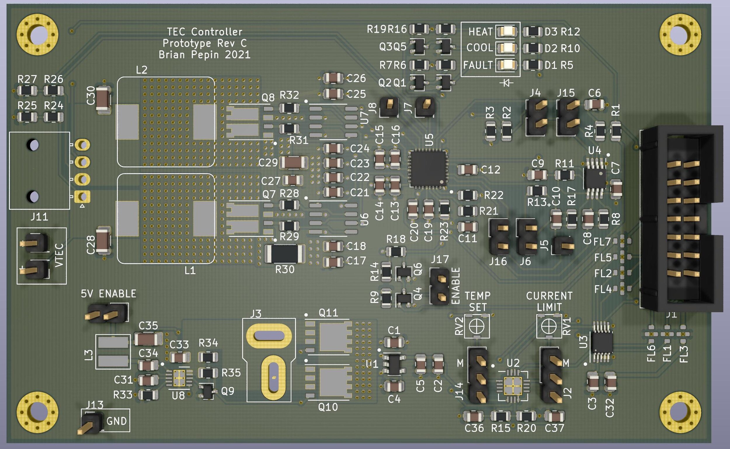
New prototype, with lots of jumper opportunities to reconfigure the board if needed.
I added a ton of jumpers and test points to this board so I should be able to see how it’s working pretty easily. There’s also a front end amplifier I didn’t include in the prototype. I didn’t want the extra parts, but calculated that I can only get an accuracy of about .1ºC without it. That’s fine for the diode pumps, but the KTP crystal will have to be temperature regulated much better than that. The extra circuit multiplies the thermistor gain by 10 so I can regulate down to .01º.
I can also put this board into a “self control” mode so I can adjust the temp set and current limit without using a microcontroller. I also moved from a 4 channel DAC to an 8 channel so I can set the current limit of each TEC through the microcontroller.
Let’s hope this one smokes less.