My second prototype TEC controller was a bit of a failure. I anticipated needing to make changes, so rather than design a board I thought I’d breadboard it with a solderless breadboard. Big mistake. A TEC controller is a high current switching power supply. My breadboard was a combination oven and radio transmitter. I couldn’t get it to work even for a few seconds reliably because EMI noise was causing shoot through on the MOFETS and frying them.
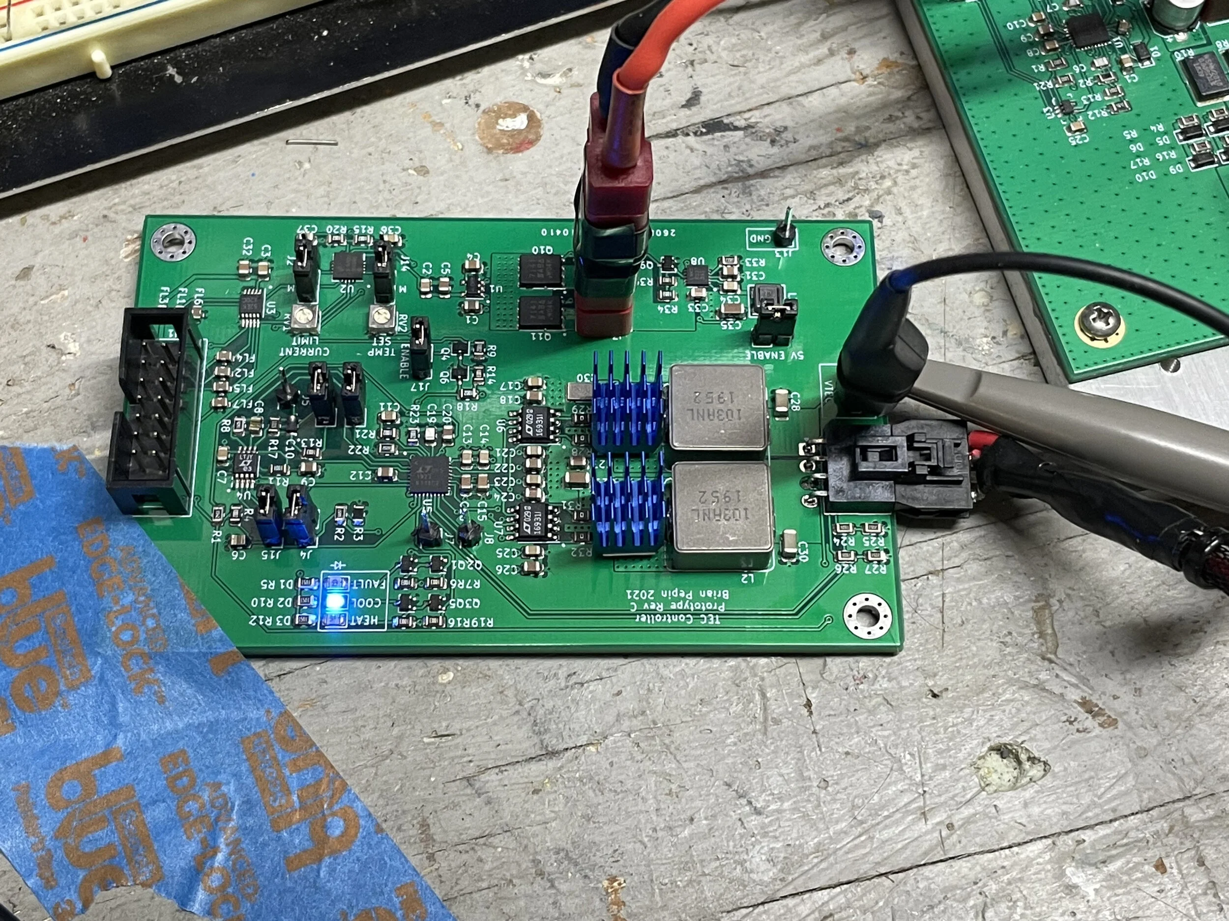
So I resigned myself to building another board. The new boards arrived last week and I soldered one up last night:

New TEC board
Note the huge number of jumpers and test points on this board. I wanted to make sure I could test and experiment with this without having to micro-solder everything. At the same time, I am keeping things like the power section tight (and four layers) to reduce noise.
As luck would have it, this board performed pretty well on the first try! The board uses a new DAC chip that I had to write software for, and it turns out I got lucky there too and it all worked. With the new DAC I can now control the TEC current via software.
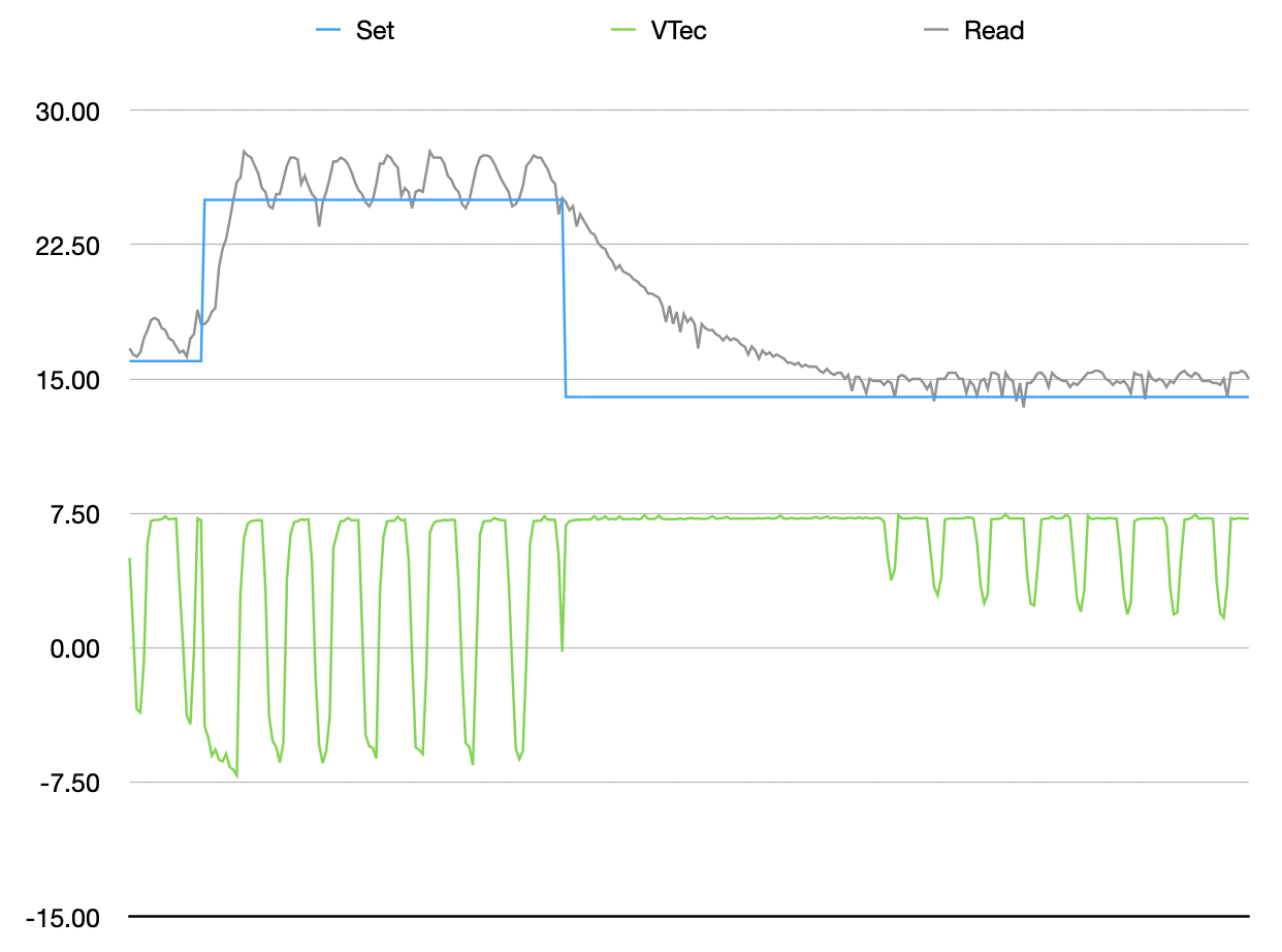
The PID controller needs to be tuned. Here’s a graph of the step response:

The green shows voltage on the tec. With this new chip this voltage is the absolute value, so you miss if it is heating or cooling. The spikes when setting higher temperatures indicate it’s oscillating between heat/cool. The low point of 10ºC never was actually achieved — the TEC stays on the whole time. Also note that the second step to 10º is worse. This is because the TEC heat sink has heated up and it can no longer maintain a low temperature. I’ll have to address this, but this doesn’t seem to be an issue with the board.
Tuning
I found one last GPIO pin on my microcontroller and bodged a signal into it that I can use to provide a + or - sign to the TEC voltage. This allows me to take the log data and send into Matlab to find the response equation for the TEC and heat sink. From there I can use the PID tuning application in Matlab to compute the PID constants and flatten all the oscillations above.
That was the theory anyway. While using this technique worked great on my last board, the numbers didn’t work out for this board. The PID tuning app kept reporting a zero proportional gain and the best match I could get for the system response was about 70%. I suspect I didn’t have enough data points. I only had a couple hundred because all the oscillations were causing the board to get quite hot.
So I guessed.
From the graph above I can see that the gain is too high. Gain on this board is 10 for the input amplifier and 100 for the error amplifier. I replaced a 100k resistor with 1M to reduce the gain of the error amplifier to 10. The results were so good I stopped tweaking. Here’s before and after graphs of the step response:
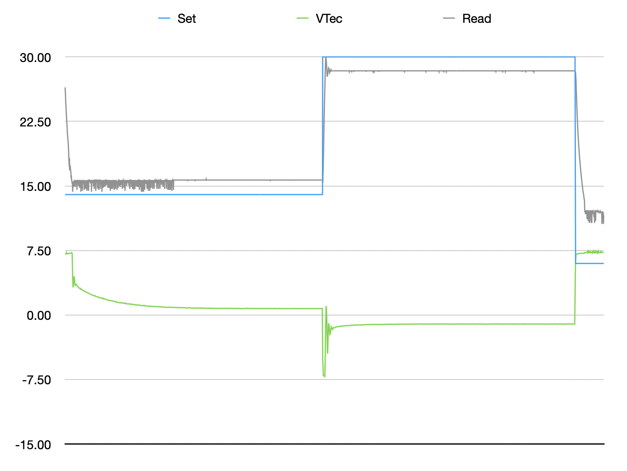
With this change I can pretty efficiently set the TEC temperature. I’ve found, however, that I struggle to keep the TEC below about 15º C. I need to regulate diode temperature so that the pump diodes emit light at 808nm. Measuring the diodes with a spectrometer I found that I was cooling them way too cold. I need to keep them at about 26º C, which turns out is very easy for the TEC to manage. The results here are good enough to move on to pumping the crystal.