
With reasonable success on the power supply it’s time to look at the next circuit I need to design. The next board is a TEC controller board to control temperatures of the laser. This laser has four components that need to have their temperature controlled:
The two pump diode arrays.
The laser crystal.
The frequency doubling crystal.
Each of these components has different requirements. Let’s dig into each of them.
Pump Diode Arrays
At the heart of the laser is two fiber-coupled diode arrays. These are used to produce a huge amount of infrared light:

Here’s the thing: while these are vastly more efficient than the alternatives, they still produce a lot of waste heat. Also, the exact wavelength of light they produce is dependent on their temperature, and I need to send the right wavelength into the Nd:YV04 crystal for this to work. How tight is this temperature tolerance? About maximum 10ºC, and for good efficiency I need to stay much closer to the target temperature (well designed lasers will hold the temperature of these devices to within .1ºC of their ideal).
The diode arrays I’m using are from Coherent and their data sheet recommends a cooling system that can remove 100W of waste heat. I have two arrays, so that’s 200W. Also, each diode array needs its own cooling system and monitor as the ideal temperatures of each might be different.
The target temperatures for these arrays should be around 14ºC for the wavelength I need.
The Nd:YV04 Crystal
This crystal is the heart of the laser and generates all the laser light. It will be a square rod about 10mm long by 3mm square. It doesn’t have any critical temperature requirements like the diode arrays, but it does have a big problem: it doesn’t transfer heat very well. This means that the interior of the crystal will be getting very hot (focusing 80W of infrared lasers on something will do that) while the outer edges of the crystal will be much cooler. The design of the crystal mount is pretty important. If the interior of the crystal gets too hot it will crack. Also, as heat builds up because the interior is hotter than the exterior, the refractive index changes and the crystal becomes a lens that messes up the laser beam.
The target temperature here should remain about 25ºC to be comfortable.
The KTP Crystal
This crystal converts the 1064nm infrared light from the Nd:YV04 crystal into a green 532nm. This conversion process is only efficient under certain circumstances. If the crystal is critically phase matched to the phase and polarization of the infrared beam, it will work efficiently when held at about 25ºC. If the crystal is non-critically phase matched the beam phase doesn’t matter, but the crystal must be held at about 200ºC. I need to research this more, but I’m striving for critical phase matching so I don’t have to produce quite so much heat.
Because of the different temperature ranges, using water cooling would be a bit of a pain as I’d need different cooling loops for the different temperature zones. Instead I’m going to use thermoelectric cooling devices. Since the pump diodes are the hardest to cool I started with them.
The Prototype
There are several off the shelf chips that can be used as a TEC controller, but not that many that can work in the current and voltage ranges I need. I settled on the ADN8831 from Analog Devices. This only requires additional MOSFETs for the H-bridge and some small support components. The downside is it can only offer a maximum of 5V to the TEC. Most of the high power TECs I’ve seen are at least 12V. But a TEC will take whatever you give git and just cool less. I need to stuff four of these circuits on a small board, so the single chip is very enticing.
The prototype I built had these specs:
On-board 5V regulator that can offer 20A of current (5A / channel).
One channel with a temperature range from 0-100ºC.
A/D and D/A converters so I can set and read the temperature from the microcontroller.
The prototype board had a lot of dead space on it because I wanted to see how the longer trace widths would affect the channels farthest from the power supply. A single TEC channel turned out to have quite a lot of other passive components besides just the driver chip and MOSFETs and I ended up having to create a board that was much bigger than my power supply board. My idea for these is they all stack on top of each other through risers and each board has a heat sink bonded to its underside. This is what the prototype looked like:

The TEC channel is on the left. The center of the board has the connector to the MCU and the DAC / ADC. The lower right part of the board is a 20A switching power supply.
Initial Testing
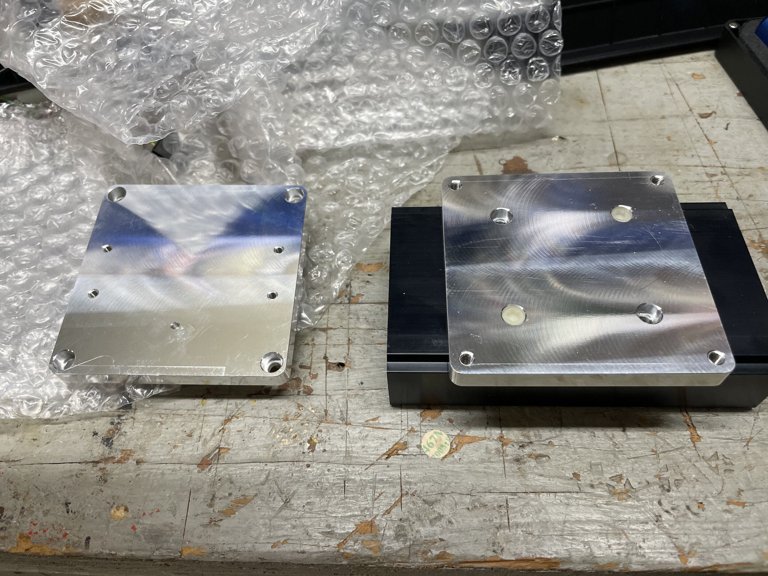
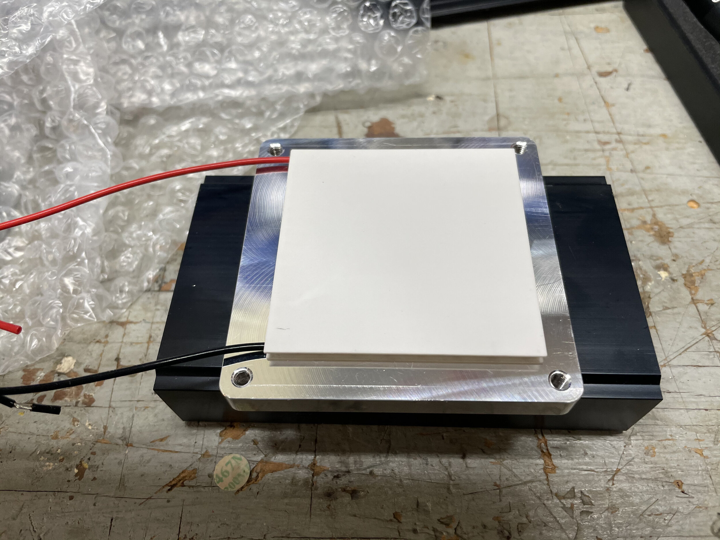
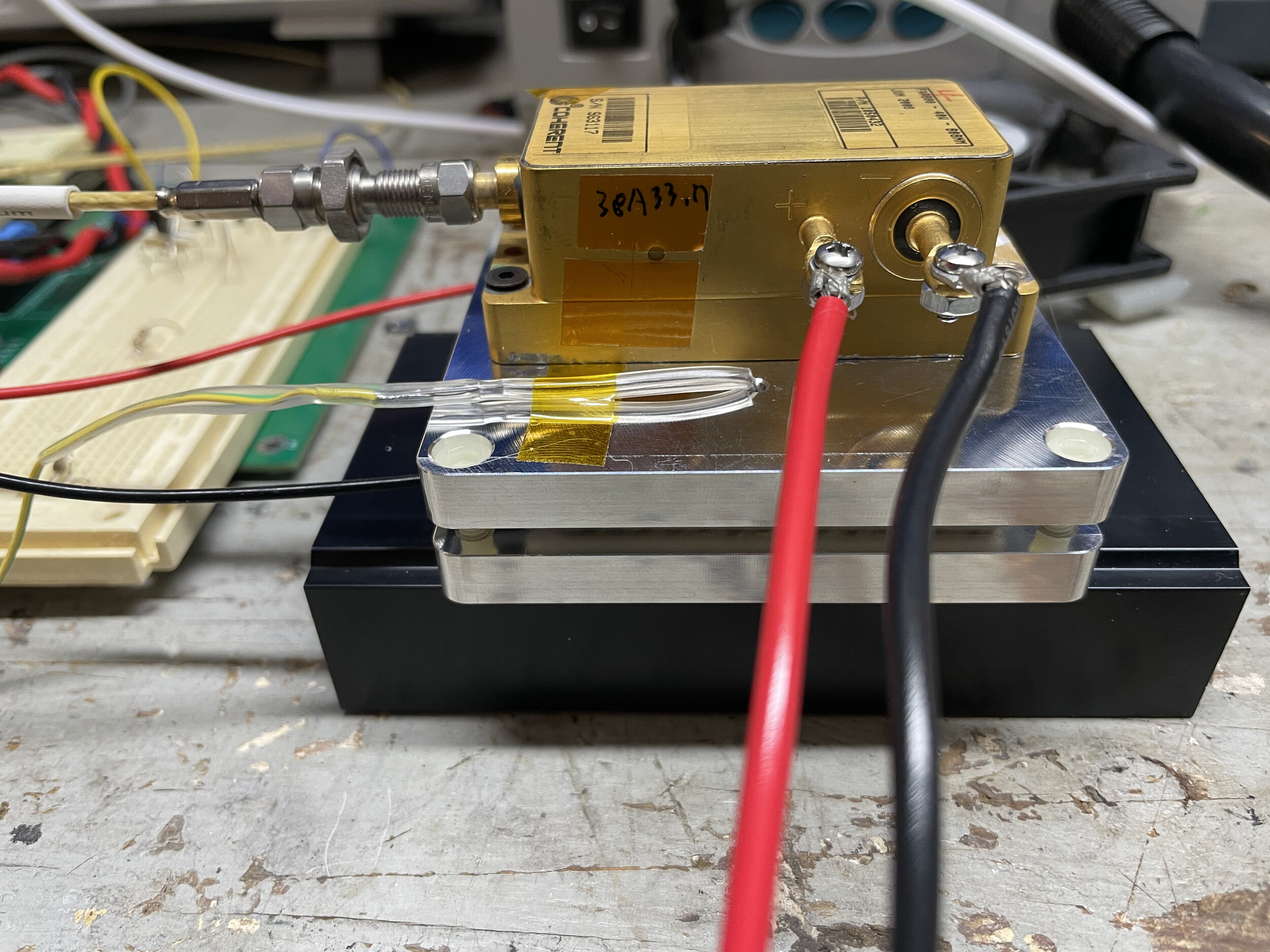
My test rig consists of custom mount I had machined and a heat sink / fan. The mount keeps the diode arrays electrically isolated because they are case positive. The machining from 3D Hubs was outstanding:
When I first started this up, the temperature control worked, but was really bad. It would oscillate around the set temperature pretty badly. A TEC cools if given a voltage in one direction and heats if the polarity is reversed. This controller would slam the TEC to full cooling, let the temperature race past the set point, and then slam the TEC into full heating mode. Not great for regulating the temperature. Not great on the batteries either. If all four TECs did this my cooling system would draw more power from the batteries than the rest of the laser.
The problem is something called “loop compensation”. Changing the temperature of a block of metal takes time and the controller has to anticipate how the thing you’re heating or cooling reacts or else you will get continued over/undershoot when regulating the temperature. The heater in your house is a great example. Most home thermostats actually regulate by overshoot. When you set the thermostat to 70º the heater turns on at 68 and off at 72. But with TECs, you can choose how much heating or cooling to apply: it’s not just on or off. You can regulate much more accurately and efficiently provided that the compensation loop is properly tuned.
The Loop Compensation Saga
The control loop on my prototype uses something called PID control. PID stands for Proportional, Integral and Derivative. Those are three components of loop compensation that make the loop respond property. Each component has a constant value, and you select electronic components that represent that constant value. The proportional part represents how aggressively the controller responds to temperature changes. The integral part allows a controller to become more aggressive over time and the derivative part allows a control to respond quickly to sudden changes. All three need to be set properly or you get the behavior I’m seeing.
The hard part is finding the constants.
One way to find the constants is to set I and D constants to zero and then keep raising P until the system oscillates at a steady state. Then, you measure the frequency of oscillation and there is a formula that estimates all the values. This is called the Ziegler-Nichols method and supposedly works well. But, it’s tedious finding that perfect value of P.
The other way of doing this is to do a lot of math. First, you need to define the equation that describes the thing you’re cooling (referred to as the “plant”). This is usually a 2nd order differential equation. Then you can go through a bunch of math to solve P I and D for that equation. If I was in a graduate level control systems theory class, this is probably what I would be asked to do. Since I’m not, I did a bit of research and found that the MatLab software package has plugins that a can both find the equation for the plant and also solve for the P I and D constants. I also learned that MatLab has a license for hobby/home use. Yeah, I’m doing that.
Armed with my new MatLab license and some handy web pages from Mathworks that showed me what to do, I added a routine to the microcontroller that allowed me to configure a target temperature and then would output the read temperature over time. I ran this with a variety of temperature changes and gathered about three hours of data (one data row every five seconds). This generates something called a Step Response curve, which I uploaded into MatLab. MatLab spat out this formula for my plant:

This equation is a second order differential equation represented in the Laplace (time) domain. I plugged this into the PID tuner app in MatLab and it presented a nice UI where I could fiddle with the constants to get the response I wanted. When I was done, it spat out constants for each.
If I was doing the PID control loop in software I would be done. But I’m doing it all in hardware so I need to convert these constants into electronic part values. But how to do it? I found a few things online but no real slam dunk equations. But MatLab re-ignited some of my long forgotten engineering math. I wrote out the Laplace domain equations for the current flowing in the compensation loop and reorganized it so it fit the “shape” of the equation for a PID controller. I was then left with four algebra equations and four unknowns. Thank you MatLab once again for symbolically solving these for me so I could skip that bit of tedious math.
I then plugged real component values into my controller circuit and ran another step response.
And holy crap it worked.
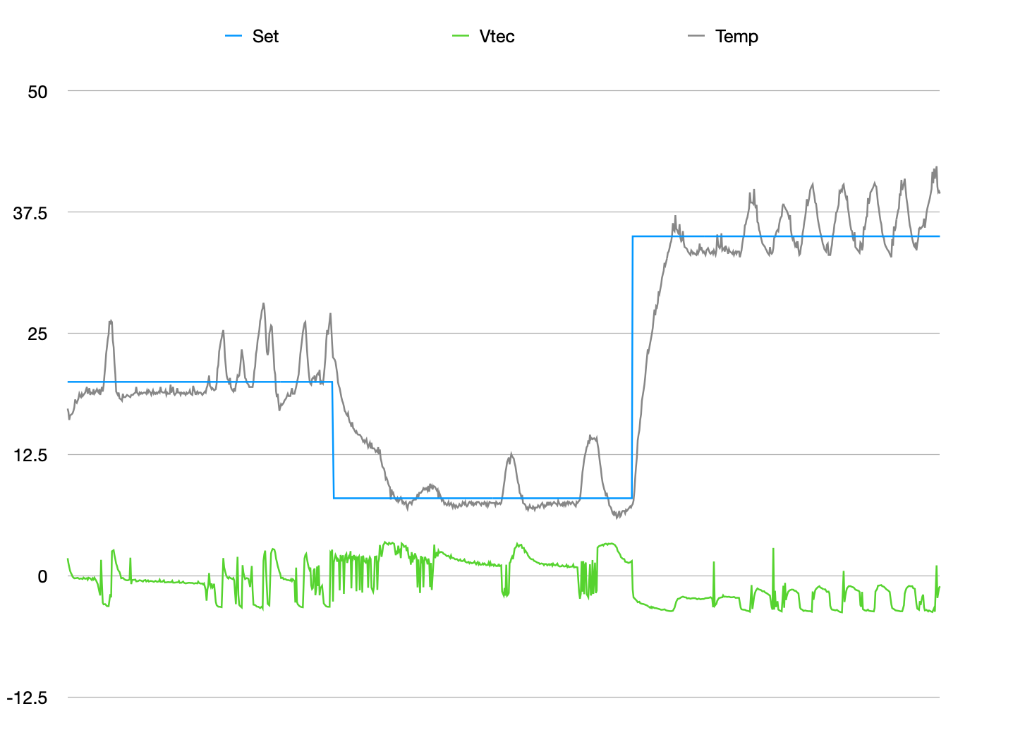
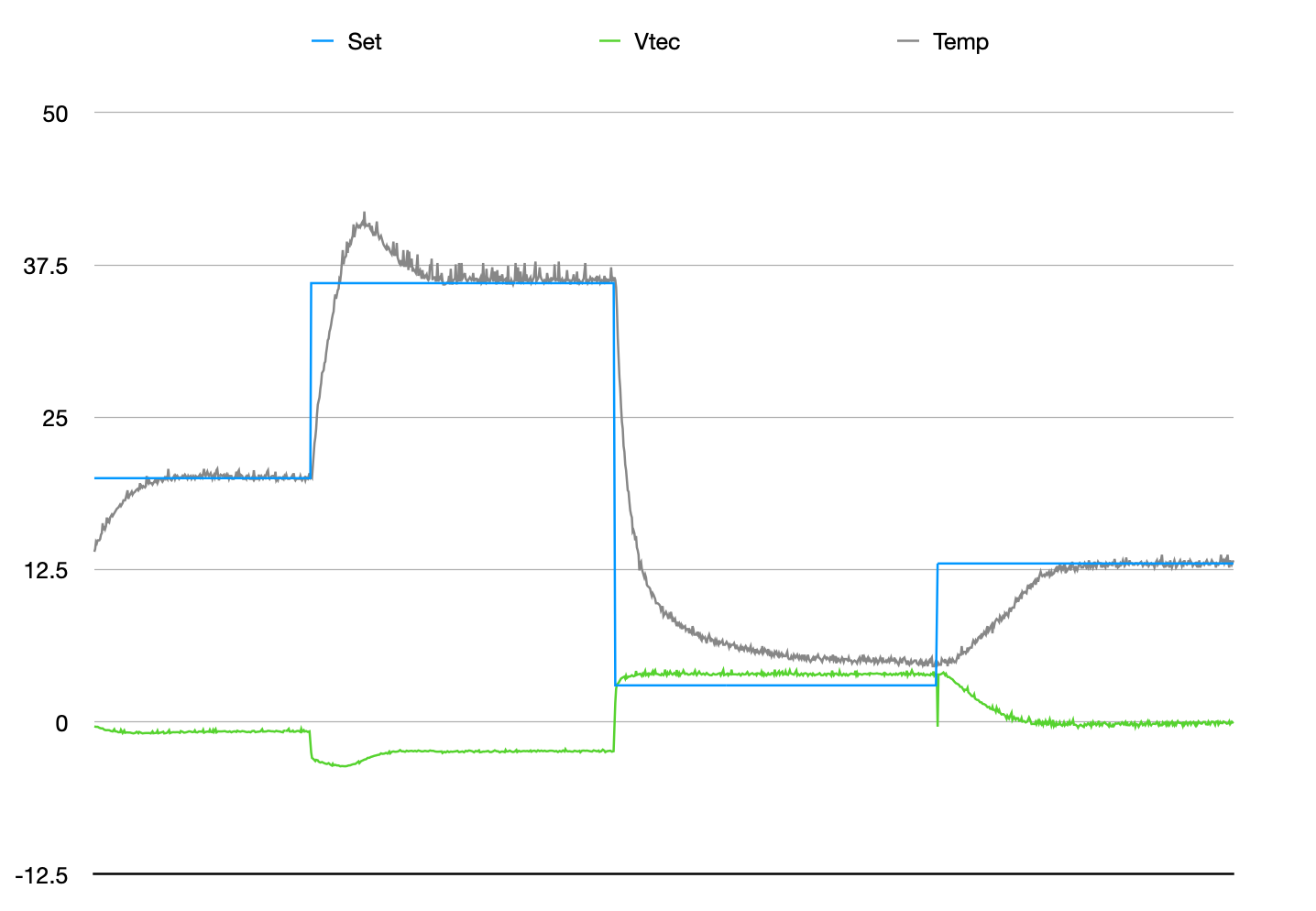
Results
So done, right? Stamp out three more of these and let’s go. Well, not so fast. So far I’ve been cooling a diode array that isn’t turned on. When running at full power, will I be able to keep the arrays cool? The answer looks like “no”. These arrays run at up to 50A of current. They start lasing at about 15A. I set an array to run at 20A and watched the temperature. Pretty good. But when I brought the array up to 30A the temperature started to pull away from my set point. While I am using a very efficient TEC cooler from Laird Thermal, it can only do so much when only given 5V to work with. I think I am going to have to redesign the whole circuit around a chip that can deal with a higher voltage. The LTC1923 looks like a good option. It also has a maximum of 5V, but it has fewer pins connected directly to the TEC outputs and can have its voltages translated. I would rather not go to a 3S LiPo pack, so I’m hoping that 8V is enough to for the TEC. On the upside, I can drive the TECs directly off the battery so I won’t need a beefy power supply like I have on my prototype. But yuck that I have to redesign the whole circuit from scratch.
One other possible holdout is the thermal interface between the diode array and the TEC. I don’t have any thermal compound here yet and this isn’t as efficient as it could be. In the world of laser parts, you typically don’t use thermal grease. Grease and optics are a bad combination. Instead, the common thermal interface material is Indium Foil. This is like tin foil but made of indium metal. It’s very soft and conforms well. It has a much better thermal conductivity than thermal paste and makes no mess. However it’s crazy expensive: a 4”x4” piece of it is over $300.00. I recently found something that might work for a fraction of the cost though. Panasonic makes these PBS Graphite Sheets that look like they have better thermal conductivity than indium. I have some coming and we’ll see how they work. I’ll still start the design work on the new circuit just in case.