
So I built a laser last year. It worked but didn’t perform great. I haven’t been sitting idle or moved on to other things. No — I’ve been understanding the physics behind what I built with an eye toward improving performance. I spent an enormous amount of time and money on this project and the result is a laser that performs about as well as something I could buy off Amazon for about $200. That stings and it’s worth fixing.
So what went wrong? Plenty. First, we need to dig into a little math and talk a bit about how electrical energy turns into green light. For the last few months I’ve been building a simulation of the laser in MATLAB. I have that simulation working pretty well and it has also accurately predicted the performance of a test laser I built on my workbench to experiment with. Let’s first discuss where I’m losing efficiency.
There are several stages of this laser. At each stage there can be a loss in efficiency. Multiply all those losses together and you arrive at an overall efficiency for the system.

The many opportunities to lose efficiency.
The pump stage converts electrical energy into light that can be used to excite the laser crystal. You can use a high-powered flash lamp or arc lamp, but those produce broad-spectrum white light and the laser crystal is only sensitive to certain wavelengths. Anything it’s not sensitive too either passes right through it or gets absorbed and turns into heat. The crystal I’m using is Nd:YVO4 and this can be excited by either 808nm light or 914nm light. It’s more sensitive to 808nm and it’s easier to find used diodes that produce this wavelength, so that’s what I’m using. This isn’t perfect: the laser crystal emits light at 1064nm and 808/1064 = .76. There’s our first major inefficiency. 76% of the light makes the laser go. 24% turns into waste heat.
There are several other opportunities for waste in the pump and yes, I do have some things that I could improve, but they are within my control.
The fundamental stage absorbs the pump light and generates a laser beam at the fundamental frequency of 1064nm. The biggest loss here is called the Quantum Efficiency, and this is a measure of how efficiently a particular type of laser crystal can convert the pump light. Nd:YVO4 has a quantum efficiency of 85.6%.
Smaller inefficiencies come from the mirrors. I’m using pretty good mirrors, but even these only reflect 99.8% if incoming light. More mirrors means more losses like this. .2% may not sound like much, but it was enough during testing that a .2% leakage out of one of the rear mirrors was enough power to melt the plastic case of a nearby piece of equipment.
The 2nd harmonic generation, or SHG, is where the bulk of the problems lie. SHG requires really high light intensities to work, and the efficiency of converting infrared to green light is quadratic with the input intensity. I’m not putting nearly enough intensity into the SHG crystal. I’m getting at best about 1% conversion efficiency here.
Measured vs Calculated Results
When the SHG crystal is removed and the laser is only producing infrared it has an overall system efficiency of 37%. My match for simulating this laser matches reasonably well with the measured output:

Fundamental Power Output
The theoretical maximum efficiency here is 65% so there is a lot that can be improved.
The SHG performance curve is worse:

Second Harmonic Power Output
Note that SHG output is not linear. This is because the conversion rate is related to the intensity on the crystal, and the intensity squares with power. Note however the measured output drops toward the end. This is likely due to thermal lensing. The MATLAB simulation I wrote does calculate lensing, but it is not yet matching measurements so I haven’t included it in the simulation.
Analysis
The key issue with SHG conversion is the intensity of the fundamental beam on the KTP crystal is too low. The current cavity focuses the beam down to 256µm on the KTP crystal, but to achieve efficient conversion it would need to be 23µm. This is a pretty hard diameter to obtain and it can cause thermal lensing issues and damage optical coatings.
You can increase the intensity in the KTP without shrinking the waist is by pulsing the laser, either by Q-switching or mode-locking.
In Q-switching you suppress laser action which causes the population inversion to increase well past what is necessary for lasing to begin. Then you suddenly allow laser action and that large population inversion creates a giant pulse.
Mode-locking is related but different. Lasers typically don’t emit a single frequency of light. They emit several frequencies that are very close to each other. This means that there are several overlapping electromagnetic waves propagating in the cavity at the same time. Normally these waves are all out of phase with each other. The laser output is therefore the sum of all these random phases. It’s a little chaotic and due to destructive interference much lower in intensity than if there was only a single wave.
In mode-locking, you force all these waves to be in phase. By doing this, much of the output is suppressed due to destructive interference, but there will be a regular cadence of pulses where the waves all align. This produces a very narrow very intense pulse. The net effect is a laser beam that has about the same power output as it did when it wasn’t mode locked, but it consists of very short intense pulses. The pulses repeat at the resonant frequency of the laser cavity itself, so typically sever hundred MHz.
Let The Experiments Begin
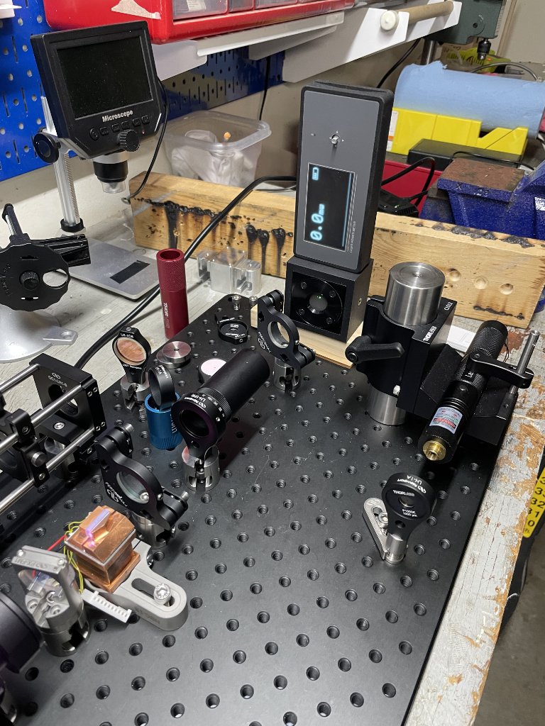
I’ve built a test laser on my workbench for experimenting. It has upper and lower “arms” with some extra space where I can place additional optics. The upper arm is where the Q-switch or mode-locking optics will go. The lower arm is where the KTP for intracavity frequency doubling will go. The setup is pictured below.

In this configuration I have the KTP outside the laser cavity. KTP won’t produce much of a green beam this way unless the output is pulsed, so this acts as a good test if things are working. I am also using a saturable absorber with an initial transmission of .8. I couldn’t get this to do much with the default beam waist of 300µm, so I am focusing the beam down to 70µm using a 100mm lens. This is a terrible way to pinch the beam waist — the lens imparts about 7% loss in the cavity, which is a pretty huge loss. It works for testing though.
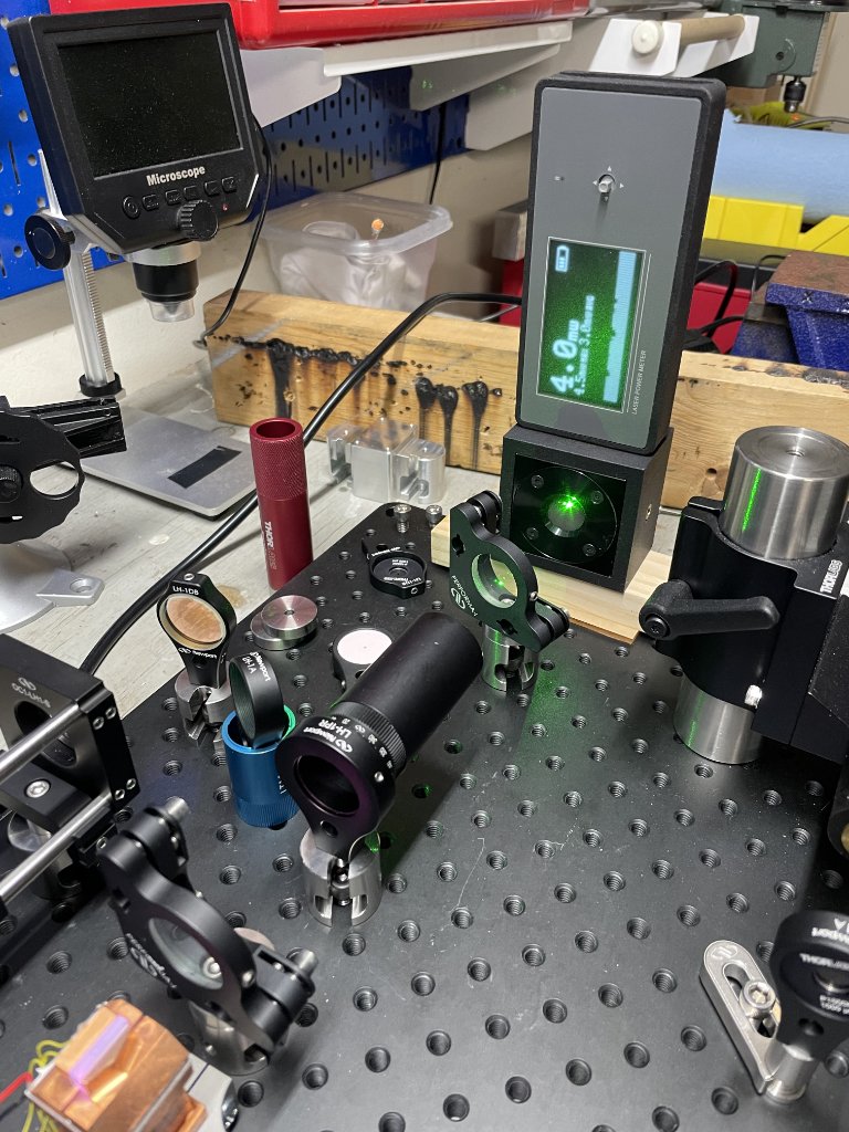
Using this setup I can switch the absorber in and out of the beam path. The power output in both cases is about the same for the infrared, but the green output is a lot different as you can see in the before and after photos below.
I bought a fancy detector from Thor Labs that can measure pulses down to 1ns. Coupling this into my oscilloscope allows me to see the pulse train and look at the shape of an individual pulse. I can’t, unfortunately, accurately measure the intensity of the pulses because the detector is sensitive and I’m adding many layers of neutral density filters to keep it from getting damaged.
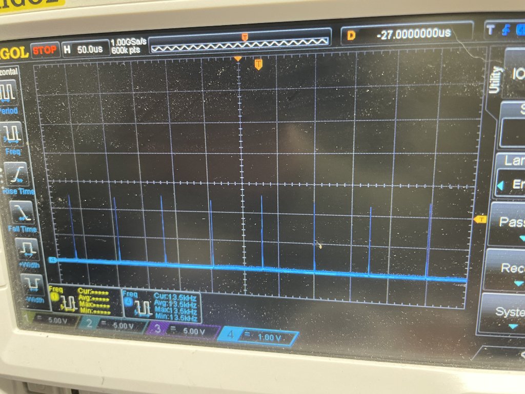
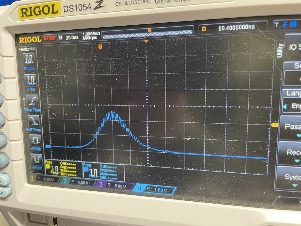
It is possible to get both Q-switching and mode locking at the same time, but that’s not what I have here. I have just Q-switching, and the pulses show there is some mode beating going on. That’s not really desirable and later runs of the laser didn’t exhibit it, so I have more I need to understand. This laser also heats up after a few seconds of operation and stops working. I think this his because thermal lensing is causing the waist in the absorber to increase. Analysis of the cavity with increased thermal lensing does show the waist in the absorber increases as lensing increases.
Trying the AOM
I also bought a used Acousto-Optic Modulator to try active modulation of the cavity. An AOM would require additional circuitry, bit it has less loss and provides more control of the Q-switch operation. Unfortunately, while I did get the AOM to modulate the beam, I couldn’t get any giant pulse formation out of it. I think this is because the AOM I have is designed for mode locking and doesn’t modulate the beam enough to get Q-switching to work. And mode locking using an AOM requires that the laser cavity length precisely match then running frequency of the AOM. My AOM runs at 68MHz, and this requires about a 2.2m cavity. I don’t have enough bench space for that.
Next Steps
Mode Locking or Q-Switching?
I need to decide if I want to pursue mode-locking. The laser runs more like a CW laser but I’m beginning to think mode-locking is hard to maintain. It’s possible to get it with a saturable absorber, but I think it fails with different pump power. Doing it with an AOM requires really precise cavity length - even temperature fluctuations can mess it up. Real world lasers that use AOMs for mode locking have some sensor apparatus in the cavity to signal when the AOM should trigger. I’m not looking for that complexity.
MATLAB
I’ve been working on the MATLAB simulation for Q-switching. Once I get this working I can calculate the intensity on the KTP and therefore the conversion efficiency. My MATLAB numbers are off now though — I’m predicting repetition rates of 130KHz (off by 10x) and pulse widths of about 190ns (off by 2x).
Lab Experiments
There are a bunch of further lab experiments to run.
By controlling the spot size on the absorber it should be possible to generate both Q-switched and mode locked pulses.
I need to try intracavity SHG. I actually have this setup now, but not with the right output coupler.
The .8 transmission of the absorber may not be optimal. A transmission of .86 or .9 may be better.
Can I hear the pulse? With a higher output it should be possible to hear the frequency of the pulse when it is hitting a surface. Of course as the output is increased so is the frequency and it’s already at 15kHz, so I may try defocusing the beam into the absorber to slow it down.