
In my spare time I like to build lasers. This sounds really cool, but really, I’m just using semiconductor diode lasers and adding optics and electronics. In reality, what I’m building is a complicated flash light.
But that’s not the point of this post. When I build one of these, I need a way of measuring the output power of the beam. For this, you need a laser power meter (LPM). Buying a power meter is the easy way out though — you can build your own. I have one I built a few years ago, but my latest lasers are too powerful to be measured by it. I need to build a new one.
My new LPM will use some nice 24 bit D/A converters controlled by an Atmel AVR chip. These are the same series of chips used by Arduino. That makes them especially nice for projects like this because there are a huge number of existing libraries written for the Arduino platform. For example, I found a nice OLED display to use:

Reading the data sheet and writing code for this display’s SPI protocol is not rocket science. However, that just gets you the ability to render pixels. That leaves a lot of manual work to create a drawing library, text rendering, font support, etc. However, because I’m using the same chip family Arduinos use I can take advantage of Adafruit’s GFX or U8Glib and get a full drawing package for free.
But my new LPM design is not the point of this post either. To program raw microcontrollers like this you need a chip programmer. To program small surface mount chips like the one I intend to use you need an ISP — an In System Programmer — which allows you to program (and reprogram) your finished circuit board.
That’s what this post is about. I couldn’t find an ISP that did exactly what I wanted so I decided to build my own. This, by the way, is how you know you truly have a hobby: When you’re building something that’s three levels deep from your actual goal you’ve entered the hobby domain.
Goals
So what makes my programmer so unique from what’s on the market that I felt compelled to design my own? Well let’s look at some of the features of my LPM design that make using standard programmers difficult.
The A/D converter and display need 3.3v. They will fry at 5 volts, which is what most programmers supply. Some programmers do support a buffer where they will accept any voltage the target is using, but they require that the board you’re programming supplies the power.
My LPM is going to have a software controlled power switch. Keeping the CPU powered and using its low power states just doesn’t cut it for something I plan to use only occasionally. I want it be able to stay in my tool cabinet for months on end without draining the battery. To do this I have designed a power switch that doesn’t need the microcontroller to be powered, but uses the microcontroller to keep the system powered once started. Long story short, if you don’t have the software uploaded into the microcontroller, there’s no way to turn the device on. That makes it hard to use a programmer that a takes its voltages from the system you’re programming.
Throughout the software process, a way to get debug / serial data out of the microcontroller is pretty important for debugging purposes. I wanted to use a very small single connection to my LPM circuit board for both programming and debugging. I decided to use a cable by Tag Connect, which allows me to have a single point of contact and has the additional advantage that there’s no physical part I have to add to the board — it’s just a pad layout with some holes.
With that set of requirements, here are the features I wanted on my programmer:
Uses off the shelf USBASP code. I didn’t want to get into the business of maintaining a fork of this open source project.
Fully buffered output / inputs that can drive a board at 5 volts, 3.3 volts, or take whatever voltage the board can supply and translate it (down to 1.8v).
Buffers that switch to high-impedance once programming is done so I can leave the programmer connected to the circuit.
A built-in FTDI USB to serial chip that connects to the UART on the AVR in the project so I can get serial debug data. This connection is active when not programming the chip.
The ability for the programmer to self-program by reversing the IO connections. Most unbuffered programmers can do this but I don’t know of any that can do it that use buffered IO — all the buffers need to swap direction.
Tiny. Ideally the size of a USB key.
The Design
I went through four iterations of this design. My first iteration was modeled after some of the USB key style programmers I’ve seen on Amazon. Only, I have a lot more parts and somewhat limited ability to solder surface mount components (things with legs are fine. things like ball-grid-array or non-visible pads are pretty hard to get right). That made the board not as USB-key shaped as I would have liked:
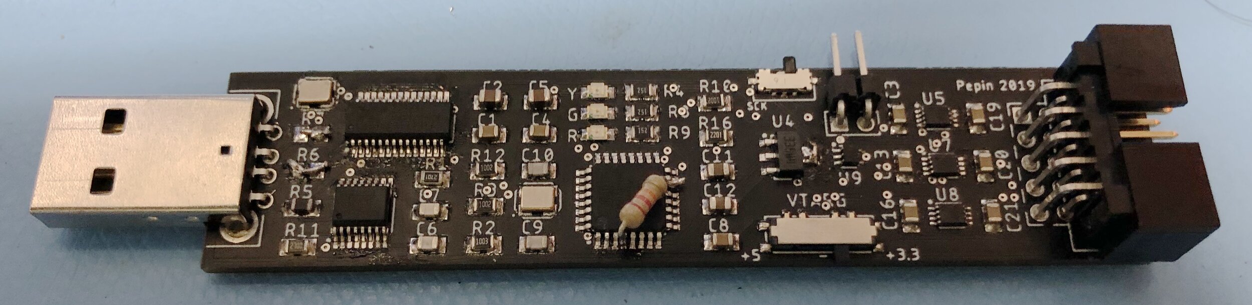
A little too long to be a USB key. Also note the jumpers and additional parts needed to make this first board work!
This design uses a 4 port USB hub (XR22404 chip in the top left), a FTDI FT230X USB to serial chip (lower left), and an I/O buffer stage on the right with three TI SN74LVC2T45 voltage translators.
There were a few problems with this design:
There is no USB ESD protection or fuses. That will likely make this board unreliable in the long term.
The buffered outputs here don’t disconnect after programming, so you need to unplug the board after programming. Not what I wanted.
Numerous circuit errors I needed to patch up with jumpers or additional parts.
Revision B
In my next revision I added the electrostatic protection to the USB interface and swapped out the voltage translators for new ones from Nexperia (74AXP4T245). The board got even longer as the Nexperia chips are larger (but they have four buffers per chip). I swapped out the USB A connector for USB-C, since this really isn’t in USB key territory any longer (and all of my uploading is done via a MacBook Pro, which only has USB-C anyway). There’s also an additional chip, U6, that’s a quad XOR gate I’m using to add the correct logic to handle tri-stating the buffers when programming is finished and controlling their direction when self programming. Here’s a comparison of the bare board to my first prototype:
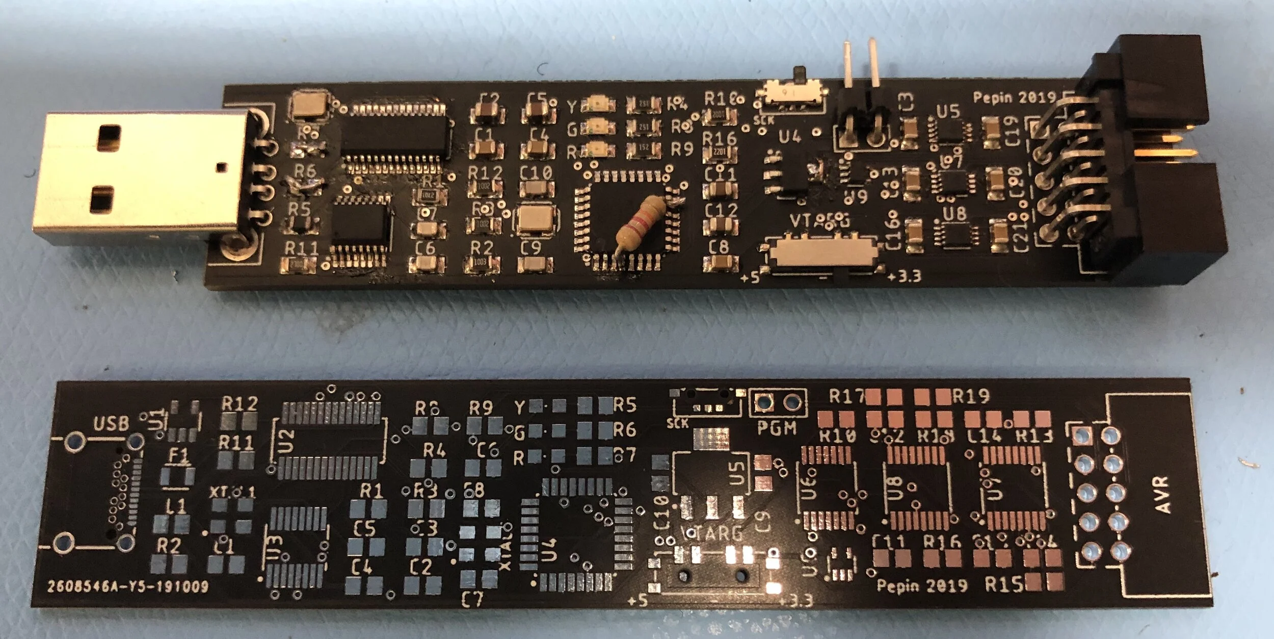
I never built this board. I ordered parts for it in October and those new Nexperia chips are still backordered. Mouser is now claiming the middle of January, some three months after my initial order date. This taught me a valuable lesson: if a part is only available from one supplier think twice. While I can get these chips from Digikey, they are special order with a minimum 3000 quantity.
I didn’t want to wait to January to find out of this board even worked, so I replaced those chips. I didn’t read the data sheet well enough for those initial TI chips I was using: they will go into tri-state mode if you ground either voltage input. That brings us to revision C.
Revision C
Revision C brings back the TI SN74LVC2T45 series for voltage translation, but I use a mix of dual input SN74LVC2T45 and single buffer SN74LVC1T45 chips. The TI chips only have one direction control pin, so I decided to go with individual buffers rather than waste unused inputs (that I would have to tie through a resistor to ground to keep from oscillating).
I did build revision C:
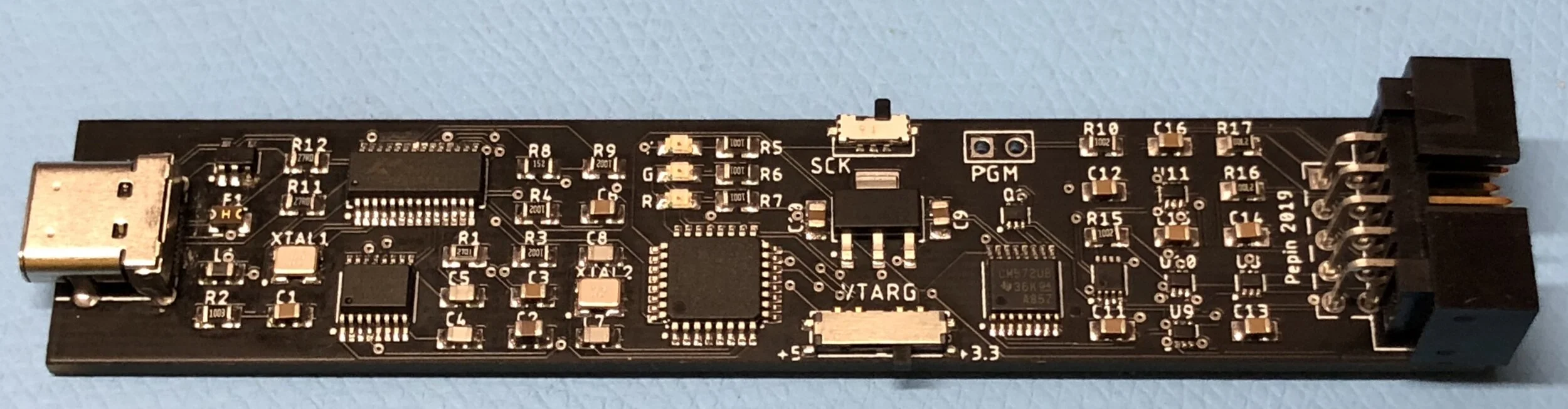
This version worked much better then my first attempt. I didn’t have to do any surgery to the board to make it work. Sort of. The only real flaw on this board is I messed up the USB C connection. On USB A, there is always 5 volts available whenever the connector is plugged in. On USB C, there is no voltage available until the port negotiates with the host. My hardware does no negotiation, so if you plug this into a USB-C port you get nothing. However, if you plug this in using a USB-C to USB-A cable it powers and works just fine. The missing “negotiation” I need is two 5.1k resistors on each of the CC pins of the USB-C connector. Hey, what’s one more revision?
We Finally have a Winner
Revision D needed no changes. I also decided it was silly to keep the board so long and thin. A little more width allowed me to greatly reduce the length. Here’s my final version:
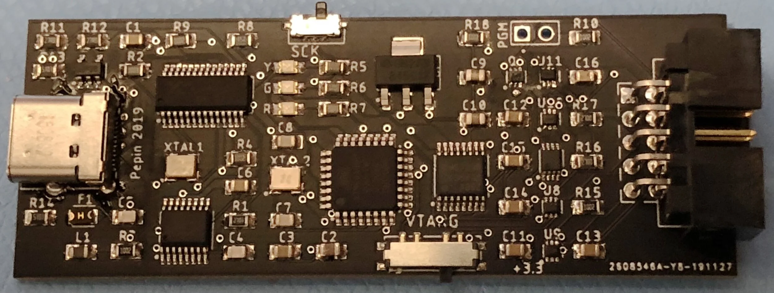
This version works great. From a “can you build it” standpoint I still find USB-C really difficult to solder reliably, and the SN74LVC1T45 chips are too small — the pins on them are .1mm wide and they are very easy to bridge. The USB hub chip I’m using (MaxLinear XR22404) also falls under the category of “often back ordered and not widely stocked across sites”. I did float the idea of replacing this, but it turns out to be the only USB hub chip I can find that uses a TSSOP format that’s (relatively) easy to solder.
Soldering SMD Components
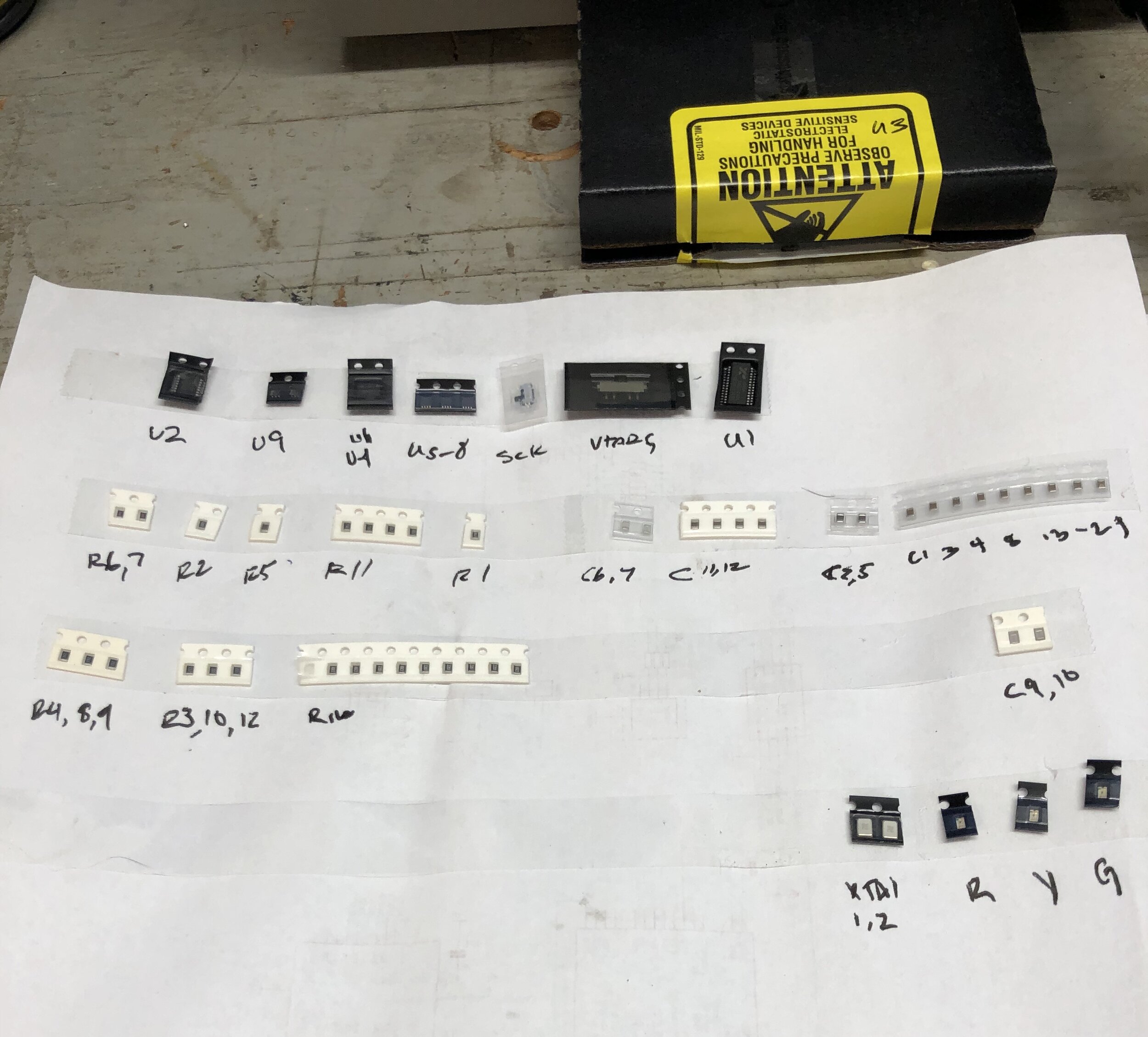
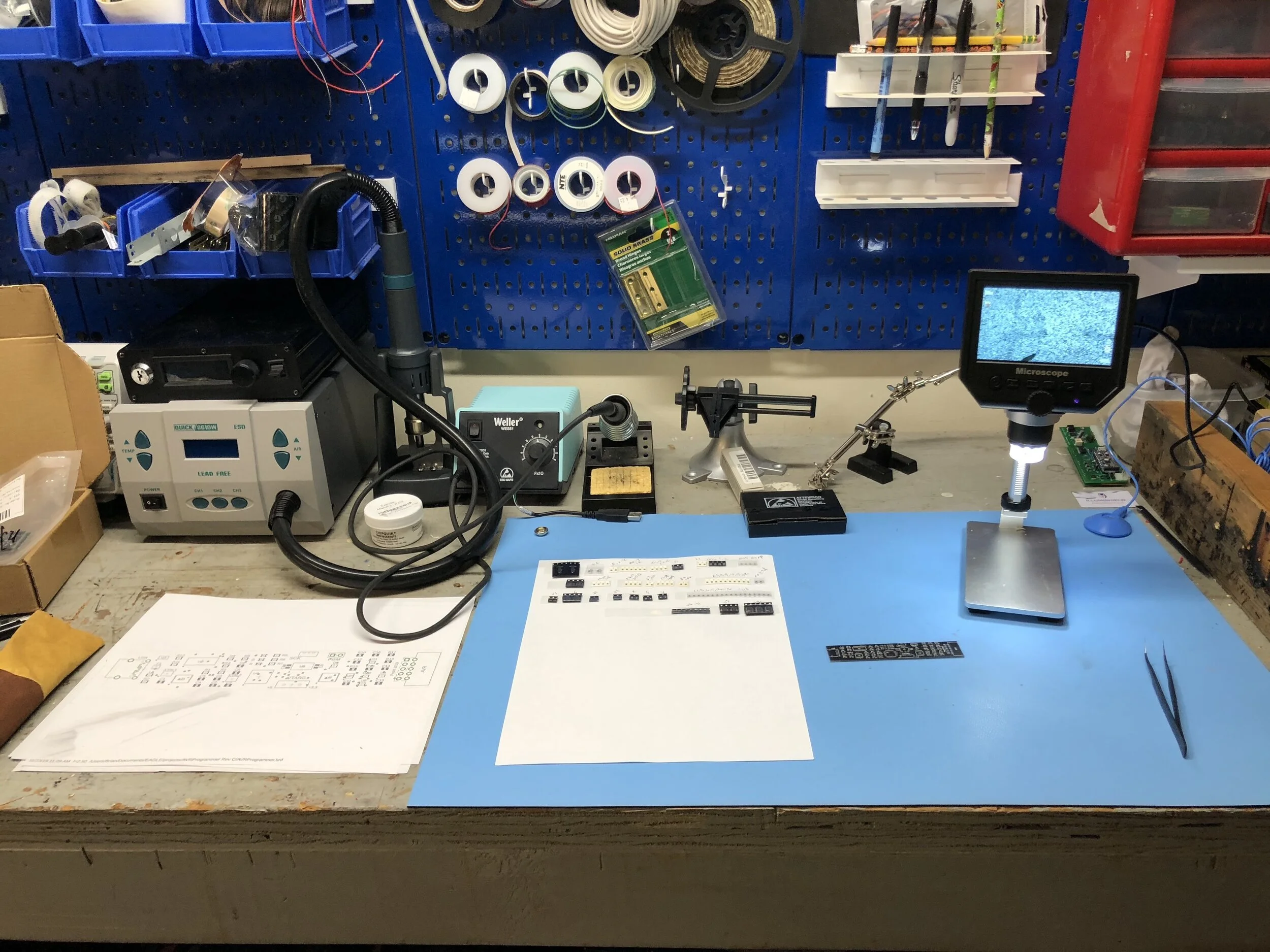
This isn’t my first project using SMD components but I’m still working through the optimal workflow. Placing all your components on a sheet clearly marked by their part name greatly helps, and if you can get boards produced from companies that offer a laser-cut silkscreen stencil for SMD solder paste your job will be a ton easier.
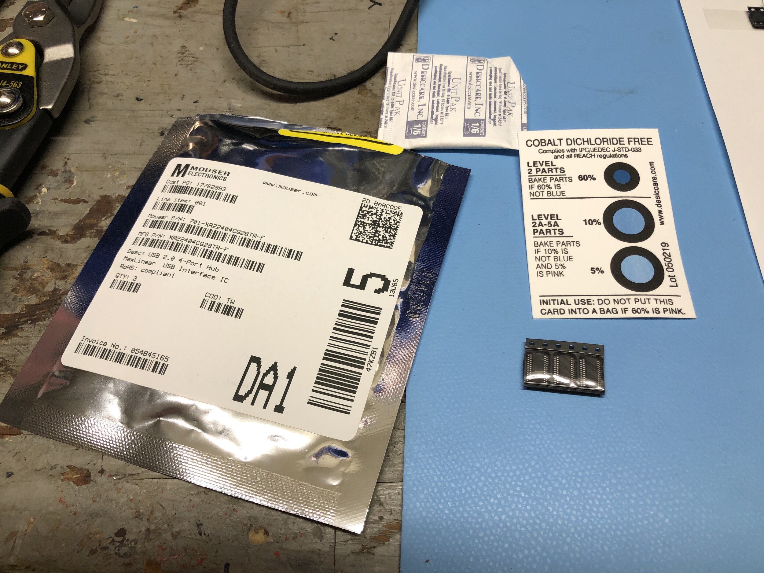
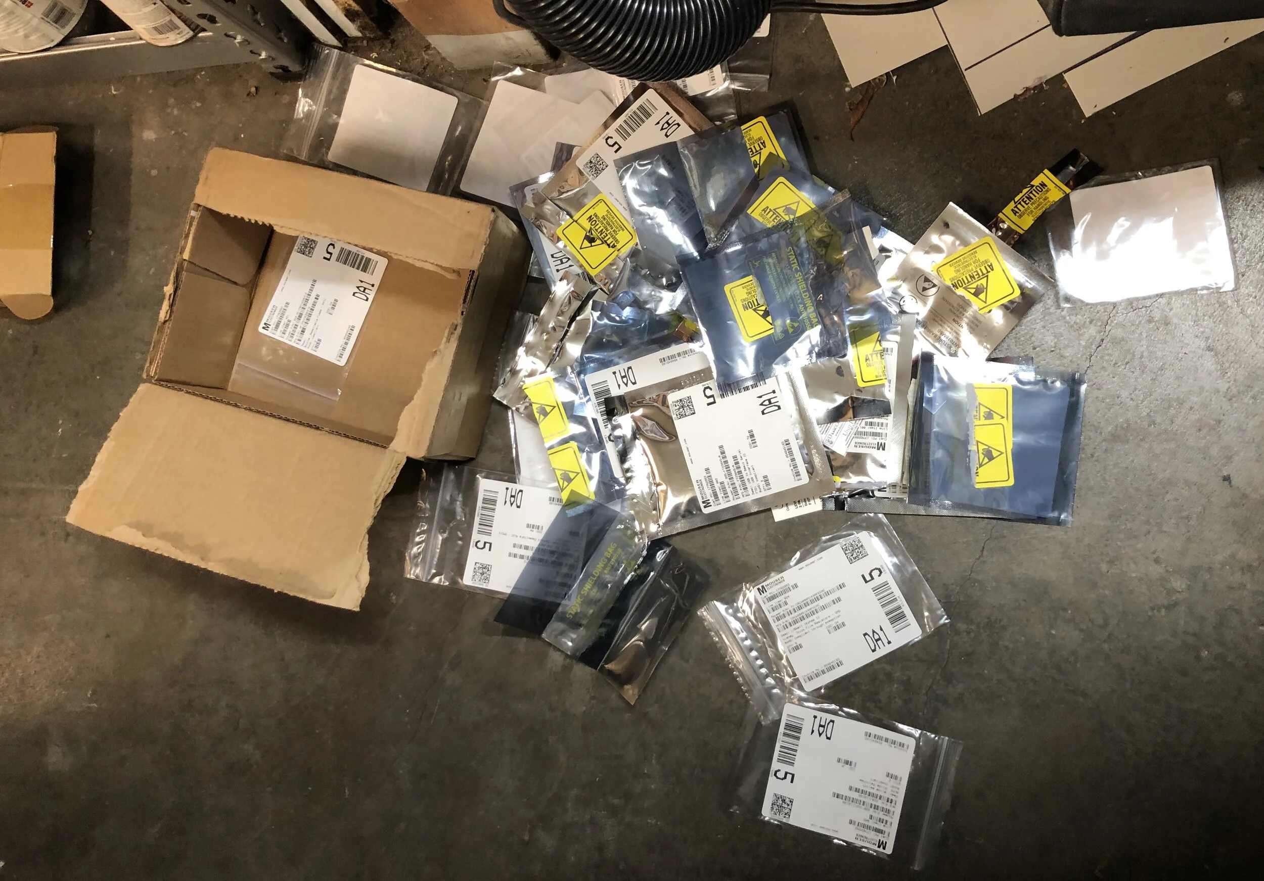
Finally, I’m consistently struck by the sheer waste buying small surface mount devices entails. A part might be 1mm square, but comes in a 4” square anti-static bag. Some even are double bagged with humidity sensors in the bags. This is a lot to throw away.
I’ve published the Eagle and Gerber files needed to build one of these for your very own on GitHub here. Now that I have a working programmer I can start on that new LPM project. Because hobbies.